HOME PAGE
ABOUT US
WHAT'S NEW
CONTACT US
APPLICATION NOTES
PRODUCTS (by Model Numbers)
PRODUCT
CATEGORIES:
Accessories
cables
connectors
mic
accessories
selectors
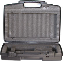
Cases and
Cabinets
DJ Products
Headphones
Karaoke Systems
Lighting
Microphones
Mixers/Amps
power amplifiers
mixing amplifiers
mixers
PA Systems
waist-band
wireless
Players
Sound Effectors
Speakers
Stands & Mounts
Trusses
Wireless Systems
|
AWM6012U - UHF
Dual-Channel
Wireless Microphone System
The Audio2000'S® AWM6012U
wireless system is a UHF dual-channel
wireless microphone system. Similar to
the other Audio2000'S®
wireless systems, various transmitter options are
provided to the AWM6012U system users as follows:
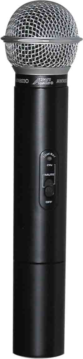
Handheld Wireless
Microphone System -
AWM6012U (AWR6012U + 2 X AWX6030's)
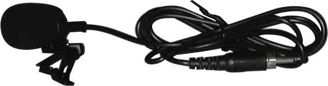
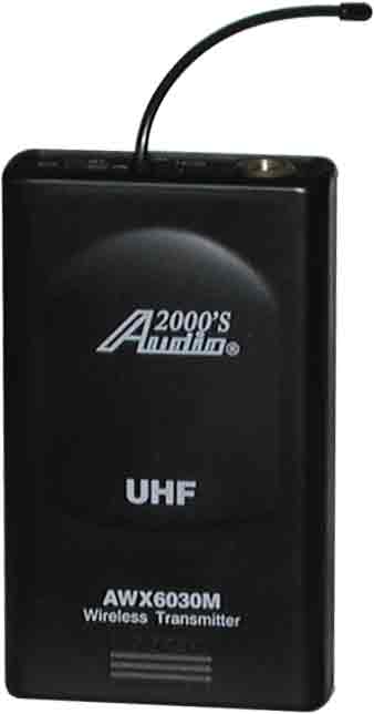
Lavaliere
(Lapel) Wireless Microphone System -
AWM6012UM (AWR6012U + 2 X AWX6030M's)
Handheld & Lavaliere
Wireless
Microphone System -
AWM6012UL (AWR6012U + AWX6030 + AWX6030M)
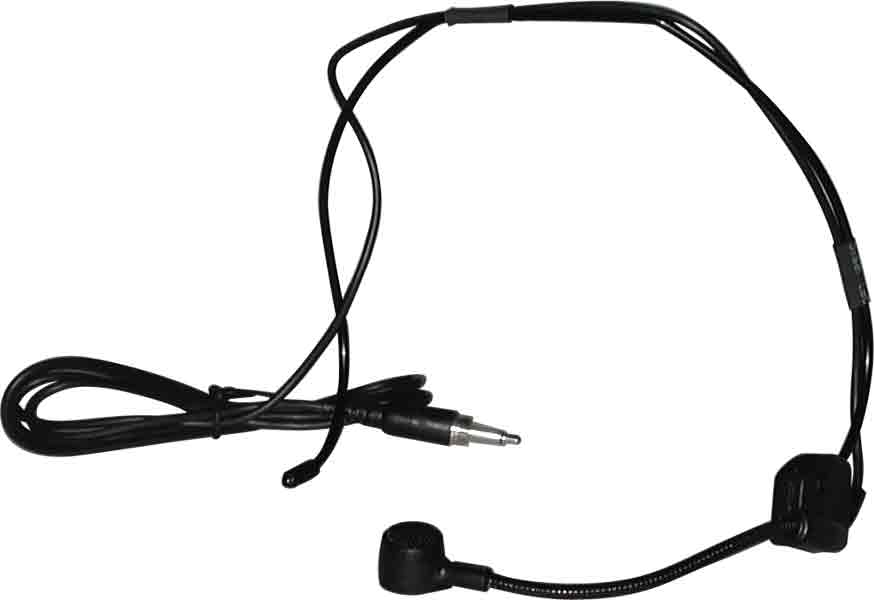
Headset
Wireless Microphone
System - AWM6012UH (AWR6012U + 2 X AWX6030H's)
Handheld & Headset
Wireless Microphone
System - AWM6012UX (AWR6012U +
AWX6030 + AWX6030H)
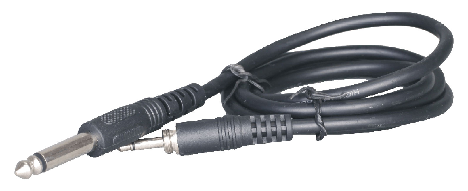
Guitar
Wireless System - AWM6012UG (AWR6012U + 2 X AWX6030G's)
Guitar
Wireless System - AWM6012UQ (AWR6012U + AWX6030G + AWX6030)
Guitar
Wireless System - AWM6012UR (AWR6012U + AWX6030G + AWX6030H)
With the exceptional RF transmission and reception, the AWM6012U
system, with a transmission range of more than 100 feet, fully delivers all the reception
and audio quality features that allow you to really enjoy the freedom of wireless without
any of the problems. A rack-mount kit is included so that the
AWM6012U system can be rack-mounted.
Engineered For Dependable UHF Systems
As all the other Audio2000'S® wireless products, the
AWM6012U system has been engineered to be dependable UHF system with a wide audio
frequency range, high S/N ratio, and outstanding performance equal to that of any
professional wireless systems costing much more. This is achieved through strict
component selection and high quality circuit design. A delicately designed silence
circuit eliminates static noise when the transmitters are either turned off or out of
transmission range. An auto mute circuit is incorporated in these systems to
effectively eliminate the popping noise when the switch is turned on or off.
System Designed For Accessibility
The AWM6012U system has been designed and manufactured to be
dependable, problem free, versatile and easy to use. The AWM6012U system is
intended to be readily accessible to everyone with exceptional performance at a preferred
and affordable price.
APPLICATIONS
Musician; disc jockey (DJ); karaoke jockey (KJ); church; school;
conference room; karaoke; home entertainment
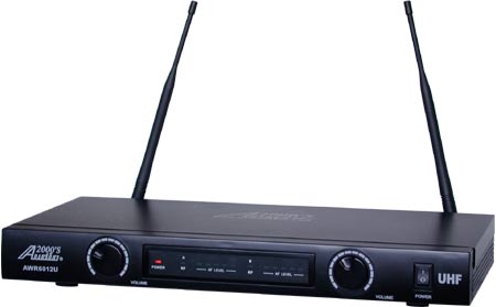
AWR6012U RECEIVER
FEATURES
* UHF Band Frequencies
* Two Independent XLR Balanced
Outputs
* One 1/4" Unbalanced Audio Output
* RF Input with Built-in RF Preamplifier to Improve S/N Ratio, Sensitivity
and Dynamic Range
* Low Noise Mixer Circuitry for Reducing interference
* Two Squelch Control Knobs
(One for Each Channel) at the Rear Panel
* 12V-18V DC Power Supply
SPECIFICATIONS
|
Carrier Frequency Range |
571
- 598 MHz |
|
Frequency Stability |
±
0.005% |
|
Receiving Sensitivity |
-105 dBm |
|
S/N Ratio |
80dB |
|
T.H.D. |
< 1% |
|
Audio Output |
Ľ” and XLR (0 – 300mV @
600 Ohms) |
|
Dimensions (W X H X D) |
15.6” X 1.7” X
7.6” (395 X
44 X 193 mm) |
AWX6030,
AWX6030M, AWX6030H & AWX6030G
TRANSMITTERS
FEATURES
* UHF Band Frequency
* High Sensitivity Cardioid Microphone Capsule
* Audio Level Adjustment Knob for the AWX6030M, AWX6030H,
and AWX6030G
* Noise Reduction Mechanism for Eliminating Handling Noise and Switch Shock
Noise
* Low Battery LED Indicator
SPECIFICATIONS
|
Carrier Frequency Range |
571
- 598 MHz |
|
Frequency Stability |
±
0.005% |
|
Modulation |
Frequency Modulation (FM) |
|
Modulation Depth |
40KHz |
|
Output Power |
30mW, Max |
|
Spurious Emission |
> 55 dB |
|
Battery |
9V Battery |
|
Current Consumption |
< 40 mA |
|
Dimensions (W X H X D)
|
Handheld: 9.3” X 2.0” X
2.0” (235 X 50 X 50 mm)
Belt-Pack: 2.6” X 4.1” X 1.0” (65 X 105 X 25 mm) |
|
Carrier Frequency Range |
571
- 598 MHz |
|
Frequency Stability |
±
0.005% |
|
Audio Frequency Response |
80 – 15,000Hz |
|
Image and Spurious
Rejection |
50dB Minimum |
|
S/N Ratio |
> 80dB |
|
Max. SPL |
110dB |
|
T.H.D. |
< 1% |
|
Service Area |
100 ft (30 M) |
|
Operation Temperature |
14
°F – 122
°F (-10
°C – +50
°C) |
Back to Top
OPERATIONS
SYSTEM OPERATION
(I) HANDHELD
MICROPHONE SYSTEM
-
-
-
-
Place one 9V battery into the battery
housing of the AWX6030 microphone with the battery polarity oriented as
indicated.
-
Turn on the power of the AWR6012U
receiver. The Power On LED light will be turned on.
-
On the AWX6030, the On/Off switch has
three positions: “ON”, “MUTE” and “OFF”. When the On/Off switch is
turned to the “MUTE” or directly to the “ON” position, the low battery
LED indicator will blink once and then stay off. If the low battery LED
indicator stays on, the 9V battery needs to be replaced. When the On/Off
switch is set to the “MUTE” or “ON” position, the corresponding channel
1 RF LED light or channel 2 RF LED light on the AWR6012U receiver will
be turned on. The corresponding channel 1 AF LED light or channel 2 AF
LED light will be on whenever the AWX6030 receives any sound while the
On/Off switch is set at the “ON” position.
-
Adjust the volume control knob on the
AWR6012U receiver to have an optimal sound quality.
-
-
-
-
Place one 9V battery into the battery
housing of the AWX6030M transmitter with the battery polarity oriented
as indicated. Connect the supplied lapel (lavaliere) microphone to the
AWX6030M transmitter.
-
Turn on the power of the AWR6012U
receiver. The Power On LED light will be turned on.
-
On the AWX6030M, the On/Off switch has
three positions: “ON”, “STDBY” and “OFF”. When the On/Off switch is
turned to the “STDBY” or directly to the “ON” position, the low battery
LED indicator will blink once and then stay off. If the low battery LED
indicator stays on, the 9V battery needs to be replaced. When the On/Off
switch is set to the “STDBY” or “ON” position, the corresponding channel
1 RF LED light or channel 2 RF LED light on the AWR6012U receiver will
be turned on. The corresponding channel 1 AF LED light or channel 2 AF
LED light will be on whenever the AWX6030M transmitter receives any
sound while the On/Off switch is set at the “ON” position. The audio
level adjustment knob is preset at midpoint. If you need to increase the
audio level, use a screwdriver to turn the audio level adjustment knob
clockwise. Turn the audio level adjustment knob counter-clockwise to
reduce the audio level.
-
Adjust the volume control knob on the
AWR6012U receiver to have an optimal sound quality.
-
-
-
-
Place one 9V battery into the battery
housing of the AWX6030H transmitter with the battery polarity oriented
as indicated. Connect the supplied headset microphone to the AWX6030H
transmitter.
-
Turn on the power of the AWR6012U
receiver. The Power On LED light will be turned on.
-
On the AWX6030H, the On/Off switch has
three positions: “ON”, “STDBY” and “OFF”. When the On/Off switch is
turned to the “STDBY” or directly to the “ON” position, the low battery
LED indicator will blink once and then stay off. If the low battery LED
indicator stays on, the 9V battery needs to be replaced. When the On/Off
switch is set to the “STDBY” or “ON” position, the corresponding channel
1 RF LED light or channel 2 RF LED light on the AWR6012U receiver will
be turned on. The corresponding channel 1 AF LED light or channel 2 AF
LED light will be on whenever the AWX6030H transmitter receives any
sound while the On/Off switch is set at the “ON” position. The audio
level adjustment knob is preset at midpoint. If you need to increase the
audio level, use a screwdriver to turn the audio level adjustment knob
clockwise. Turn the audio level adjustment knob counter-clockwise to
reduce the audio level.
-
Adjust the volume control knob on the
AWR6012U receiver to have an optimal sound quality.
-
-
-
-
Place one 9V battery into the battery
housing of the AWX6030G transmitter with the battery polarity oriented
as indicated. Connect the supplied guitar to the AWX6030G transmitter.
-
Turn on the power of the AWR6012U
receiver. The Power On LED light will be turned on.
-
On the AWX6030G, the On/Off switch has
three positions: “ON”, “STDBY” and “OFF”. When the On/Off switch is
turned to the “STDBY” or directly to the “ON” position, the low battery
LED indicator will blink once and then stay off. If the low battery LED
indicator stays on, the 9V battery needs to be replaced. When the On/Off
switch is set to the “STDBY” or “ON” position, the corresponding channel
1 RF LED light or channel 2 RF LED light on the AWR6012U receiver will
be turned on. The corresponding channel 1 AF LED light or channel 2 AF
LED light will be on whenever the AWX6030G transmitter receives any
audio signal while the On/Off switch is set at the “ON” position. The
audio level adjustment knob is preset at midpoint. If you need to
increase the sound level, use a screwdriver to turn the audio level
adjustment knob clockwise. Turn the audio level adjustment knob
counter-clockwise to reduce the sound level.
-
Adjust the volume control knob on the
AWR6012U receiver to have an optimal sound quality.
OPERATION NOTES
-
The AWX6030, AWX6030M, AWX6030H, or
AWX6030G needs to be turned off before changing the 9V battery.
-
Signal dropout or unexpected noise may
be caused by a low battery or by an excessive distance between the
transmitter and the receiver. If you encounter signal dropout or
unexpected noise, please check the battery first. If battery is still
fresh, try to readjust the antennas on the AWR6012U receiver.
-
Avoid placing the receiver in a corner
to prevent any RF reception deterioration.
-
Avoid placing the receiver antennas
close to an obstruction or close to any metal surface.
-
Try to place the receiver as far away
from any digital equipment, including computers and some CD players, as
possible.
-
If more than one AWM6012U wireless
microphone systems are stacked together or placed in a rack, do not let
the antennas touch each other or cross each other.
-
Before the AWM6012U is to be used in a
new location, place the AWR6012U receiver at the intended location and
walk-through the area with the transmitter to locate any radio frequency
blind spot, where a momentary loss of sound or short period of noise may
occur whenever the transmitter is moved to this spot.
-
Do not drop the transmitter on the floor
or strike the transmitter with any object.
-
Always turn off the transmitter and
remove the battery if the transmitter is not to be used for a period of
time to prevent the transmitter from being damaged by a leaking battery.
Back to Top
TROUBLESHOOTING
PROBLEM
|
POSSIBLE CAUSES
|
SOLUTIONS
|
|
No sound. |
Receiver is
off. |
Turn on
receiver. |
|
Transmitter
power switch is off. |
Turn on
transmitter power switch. |
|
No battery or
bad battery in transmitter. |
Insert or
replace battery. |
|
Wrong polarity
or faulty battery contact |
Correct
polarity or battery contact. |
|
Receiver audio
cable is missing or defective. |
Connect, repair
or replace cable. |
|
Short range or
signal dropouts. |
Low transmitter
battery level. |
Replace
transmitter batteries. |
|
Poor antenna
reception. |
Reposition
antenna or receiver. |
|
Faulty
transmitter antenna. |
Return
transmitter to factory or authorized service station for service. |
|
Too many
obstacles between the receiver and transmitter. |
Move the
obstacles or move the receiver away from nearby metal objects. |
|
Signal
Interference. |
Another
wireless microphone operating on the same frequency |
Use a wireless
microphone with different operating frequency. |
|
Placement too
close to a digital signal processor or similar device (CD player,
stage lighting, etc.). |
1.
Select another operating frequency
2.
Move receiver to another location |
|
External
electromagnetic field source |
|
|
Distortion. |
Low transmitter
battery level |
Replace
transmitter batteries. |
|
AF Level
control on the transmitter set too high, overloading the receiver
circuit. |
Turn down the
AF Level control on the transmitter. |
|
Volume control
on the receiver set too high, overloading the subsequent sound
device input. |
Turn down the
volume control on the receiver. |
|
Momentary loss
of sound when transmitter is moved around the performing area. |
Radio frequency
(RF) blind spots. |
Reposition the
receiver. If the momentary loss of sound problem cannot be removed,
walk through the performing area and mark “Blind” spots. Avoid
these “Blind” spots during performance. |
|
Low sound
level. |
Faulty cable
connection. |
|
|
Receiver volume
control set too low. |
|
|
Sound levels
between two microphones are different. |
The receiver
volume control and/or the microphone AF Level control need to be
adjusted. |
1.
Adjust the transmitter gain control as necessary.
|
Back to Top
|
